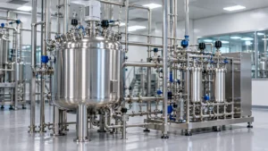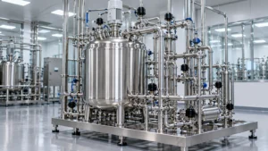
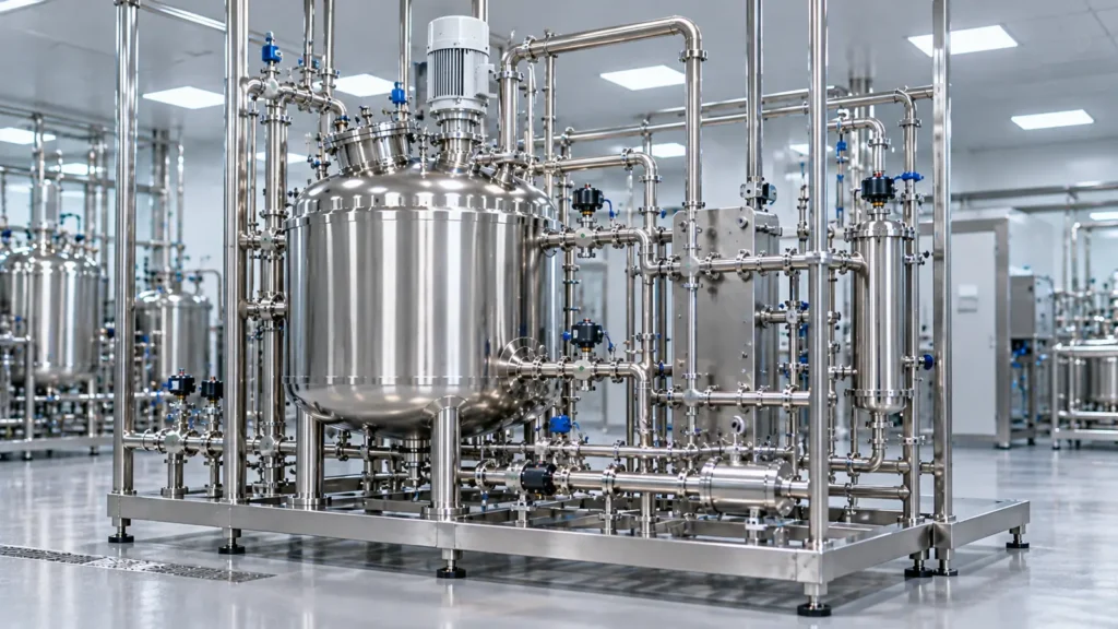
Clean utilities for process skids are the water, steam and gas supplies that touch product contact surfaces or define the sterile boundary of a skid. Water for injection (WFI), purified water (PW), clean steam, compressed air and process gases are generated and distributed by the plant. The skid is where they are used. Most commissioning delays in this area come from the boundary between the two, where each side assumes the other has defined the requirement.
This post is about that boundary: what to define in the URS, what the skid supplier should document, and what to verify at FAT, SAT and qualification. It does not cover the design of utility generation plants.
Where clean utilities for process skids end and the plant begins
The utility generation and distribution system belongs to the plant. The skid starts at a defined connection point, normally a valved and documented tie-in. Everything downstream of that point, including the piping on the skid, filters, traps and drains, is part of the equipment the supplier designs.
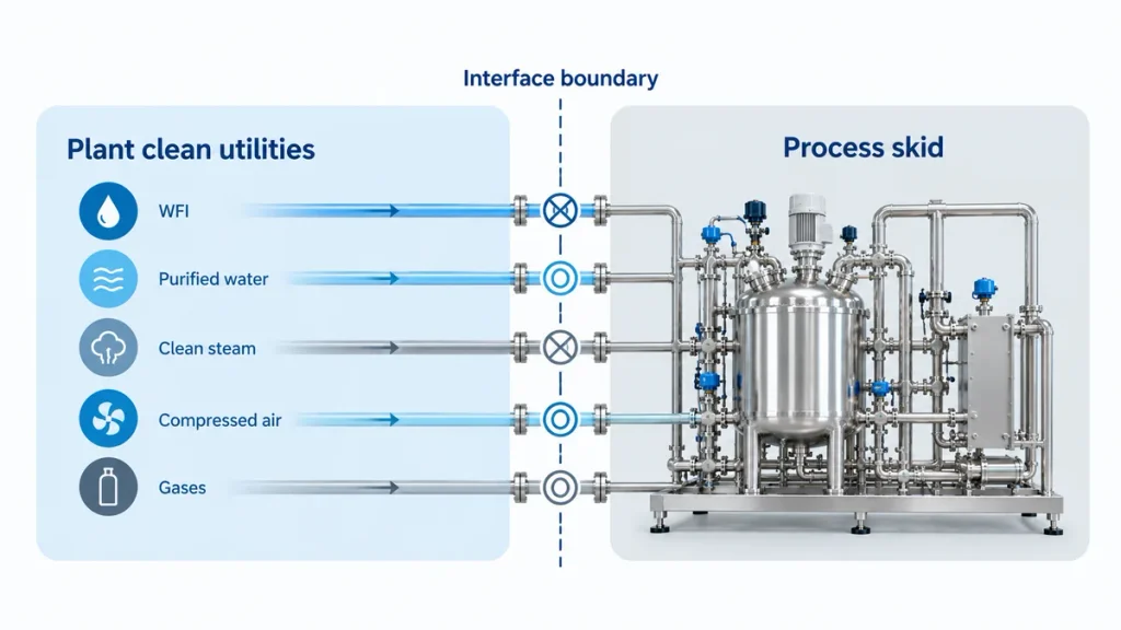
The boundary matters for three reasons.
- Responsibility. Whoever owns the supply owns the quality of what arrives at the tie-in.
- Qualification. EU GMP Annex 15 section 8 expects utilities that affect product quality to be qualified. The skid cannot be tested against a utility that has not been qualified.
- Design. The pressure, temperature, flow and quality at the tie-in set the design basis for the skid piping and its instruments.
EU GMP Annex 1 sections 6.1 to 6.6 expect utilities to be treated on a risk basis, with installation records, and paragraph 5.6 expects the qualification, monitoring and planned maintenance of water systems and other supporting systems. The skid supplier’s job is to make the interface clear enough that those records can be written. For the wider Annex 1 context, see EU GMP Annex 1 equipment requirements.
Utility interface table
Use the table as a starting list for the URS. Each row needs a value or range from the plant, which the skid supplier then confirms.
| Utility | What to define at the interface | What to check at FAT | What to check at SAT |
| WFI | Connection type, pressure and temperature range, use as product or rinse water, sampling point location | Piping slopes, drain points, absence of dead legs, instrument calibration | Connection to the qualified loop, flushing records, sample results from the use point |
| Purified water | Connection type, pressure range, use for cleaning cycle stages | Cleaning cycle sequence and flow paths | Water quality at the use point, cycle performance |
| Clean steam | Pressure range, condensate drainage, trap position, sterilisation temperature requirement | Temperature sensor positions, trap and drain arrangement, SIP cycle record | Steam quality checks, SIP temperature mapping at the slowest-to-heat locations |
| Compressed air and process gases | Pressure range, filter grade and location, vent and purge needs | Filter housing design, integrity test access | Filter integrity test records, supply quality |
| Drains | Receiving point, pressure and temperature of discharge, air break requirements | Drain slopes and break points | Drain performance under full cycle load |
Where the supplier’s FAT area can supply a given utility, the test is done there. Where it cannot, the behaviour is simulated at FAT and confirmed at site, so the SAT protocol must name which tests moved and why.
WFI and purified water at the skid
Annex 1 sections 6.7 to 6.15 describe the expectations for water systems. Several of them shape what happens at the skid:
- Dead legs are avoided in distribution and at use points.
- Flow is turbulent, to discourage biofilm formation.
- WFI is produced by distillation or by an equivalent method such as reverse osmosis combined with electrodeionisation, ultrafiltration or nanofiltration.
- Circulation above 70 C is given as an example of a measure to control microbial growth.
- Continuous monitoring of parameters such as total organic carbon (TOC) and conductivity is expected in the system.
The skid does not control the loop, but it can undo the loop’s quality. A long branch off a use point, a poorly drained low point or a hose connection can reintroduce the problem the loop was designed to avoid. Our guide to CIP/SIP skid design and dead leg control describes the layout rules. If WFI or PW is used in the final rinse of a cleaning cycle, the rinse quality becomes part of the cleaning validation, as set out in cleaning validation for pharmaceutical equipment.
Clean steam for sterilisation
Clean steam, also called pure steam, is used for steam-in-place of product contact parts. Plant steam is made with boiler treatment and is not intended to contact product surfaces. Annex 1 paragraphs 6.16 and 6.17 set the expectations for pure steam: the condensate should meet the WFI monograph, and the steam should be checked for non-condensable gases, dryness fraction and superheat. The Annex does not make routine microbial testing of the condensate mandatory.
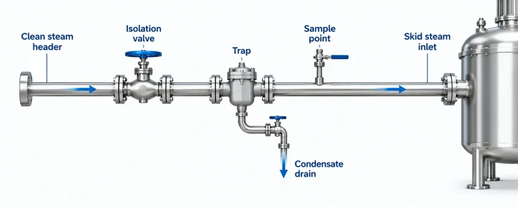
These three physical checks decide whether sterilisation works. Non-condensable gases insulate surfaces and leave cold spots, wet steam lowers the effective temperature, and superheated steam does not transfer heat in the same way as saturated steam. A skid can pass SIP at FAT on a test steam supply and then fail at site, because the site steam is different. The SAT protocol should therefore include a record of steam quality at the tie-in, taken before the skid is tested.
For the steam-in-place process itself, see our posts on the SIP system and the clean-in-place system.
Compressed air and process gases
Gases that contact the product, or that vent from a sterile vessel, are part of the sterile boundary. Annex 1 paragraphs 6.18 and 6.19 expect a sterilising grade filter, 0.22 micron, at the point of use for gases that contact product or product contact surfaces. The skid supplier typically provides the filter housing and its position. The plant provides the supply and its quality.
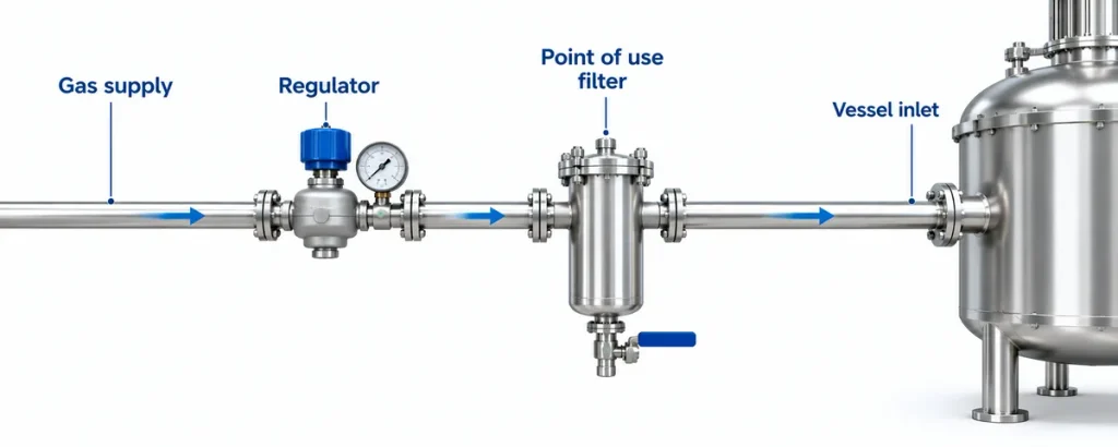
Things to settle in the URS:
- Which gas lines need a point-of-use filter, and which only need an inline filter upstream.
- Whether the housing can be steamed in place and drained.
- How the filter integrity is tested, and whether the test connection is accessible without breaking the sterile boundary.
- How the vent filters on vessels are protected from condensate and wetting.
Qualify the utility before you test the skid
A frequent schedule error is to plan SAT for the skid before the plant utility is qualified. Annex 15 section 8 expects utilities to be qualified, and the skid tests then rely on that status. If the utility is not ready, SAT either waits or runs on an assumption that has to be revisited later.
- Confirm that the utility system is installed, documented and in a qualified state, or has a documented plan to be.
- Record the actual pressure, temperature and quality at the tie-in.
- Run the skid tests against those recorded values.
- Keep the utility records in the qualification package for the skid, so QA can trace the link.
The broader sequence of design review, FAT, SAT and qualification is covered in the FAT and SAT guide and the process skid procurement checklist.
Who owns what
| Item | Plant (manufacturer) | Skid supplier |
| Utility generation and distribution | Designs, builds, qualifies | Not involved |
| Tie-in connection point and valve | Defines the position and type | Confirms and documents |
| Pressure, temperature and quality at the tie-in | Provides and records | Designs the skid for the stated values |
| Piping, traps, filters and drains on the skid | Reviews | Designs, builds, tests |
| Instrument calibration on the skid | Verifies at SAT | Calibrates and documents |
| Utility qualification records | Owns | Receives copies for the test records |
Utility specification checklist for the URS
- Utilities required, with the use of each (product, rinse, sterilisation, motive).
- Pressure, temperature and flow ranges at the tie-in, with maximum and minimum values.
- Quality standard each utility must meet at the tie-in, and how it is verified.
- Tie-in connection type, position and isolation.
- Filters needed at the skid, with grade and location.
- Drain receiving point and discharge conditions.
- Instrument tags and calibration requirements for utility measurements.
- Documents to be supplied: P&IDs, utility interface list, test records.
If you are drafting a URS from scratch, the URS guide for a sterile manufacturing vessel skid can be used alongside this checklist.
Common problems found at SAT
- Utility not qualified on arrival. The skid is ready, the utility is not, and the schedule slips.
- Different steam at site. SIP passed at FAT on test steam and fails at site on plant steam quality.
- Missing sample points. QA wants a sample from the use point and no valve was specified.
- Pressure outside the stated range. The design was based on a value that the utility cannot deliver in practice.
- Drain backpressure. The drain line cannot take the discharge from a full cycle.
Frequently asked questions
What is clean steam in pharmaceutical manufacturing?
Clean steam, also called pure steam, is steam whose condensate meets the water for injection specification. It is used to sterilise product contact surfaces, for example in steam-in-place cycles. Annex 1 paragraphs 6.16 and 6.17 describe the expectations.
What is the difference between plant steam and clean steam?
Plant steam is produced for heating and may contain additives used to protect the boiler. It is not intended to contact product or product contact surfaces. Clean steam is generated to a defined quality and is distributed in dedicated piping.
Does the quality of the final rinse water matter for cleaning validation?
Yes. The final rinse is the last thing to touch the surface before the next batch, so its quality and the way it drains are part of what the cleaning validation has to cover.
Who qualifies the utilities, the plant or the skid supplier?
The plant. The skid supplier qualifies or tests the skid. The utility qualification records are an input to the skid tests, not a deliverable from the supplier.
Do vent filters on sterile vessels need to be sterilising grade?
Vent filters on sterile vessels are part of the sterile boundary, so they are normally treated as sterilising grade filters with integrity testing. Annex 1 paragraph 8.88 addresses vent filter integrity. The decision for each filter should be documented in the plant’s contamination control strategy.