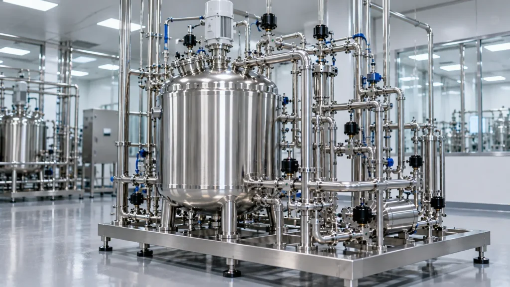
The revised Annex 1, published in August 2022 and in operation from 25 August 2023, changed the way sterile manufacturers are expected to justify their equipment. The EU GMP Annex 1 equipment requirements are not a list of approved designs. They ask for a design that is documented, controlled and linked to a contamination control strategy (CCS), with monitoring as confirmation rather than the main defence.
This post is about the process equipment side: vessels, skids, CIP/SIP systems and their interfaces. It does not cover cleanroom classification, RABS, isolators or environmental monitoring programmes, which need their own treatment.
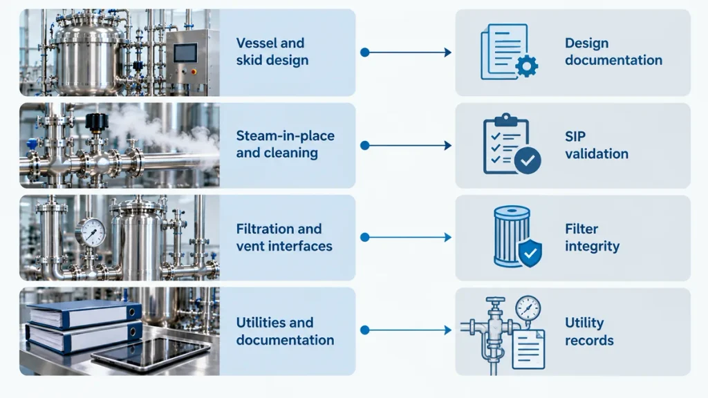
What Annex 1 changed for process equipment
Three shifts matter to equipment buyers.
- Design comes first. Paragraph 2.2 states the principle that monitoring alone does not give assurance of sterility. The equipment has to be designed so that contamination risks are controlled before any sample is taken.
- The CCS is a site document. Paragraph 2.3 expects a CCS that covers the whole facility. Equipment is one input to it, so the supplier’s design information has to be usable by the people who write and maintain the CCS.
- Documentation is part of the requirement. Paragraph 5.1 expects a detailed description of the equipment, including process and instrumentation drawings, and paragraph 5.2 expects the user requirement specification to define the monitoring needs.
If you are building or revising the URS, our guide to writing a URS for a sterile manufacturing vessel skid shows how to capture these points.
EU GMP Annex 1 equipment requirements mapped to a vessel or skid
The table below links Annex 1 paragraphs to the questions a project team should be able to answer about a vessel, skid or CIP/SIP system. It is a reading aid. The Annex itself, linked at the end of this post, is the authority.
| Annex 1 reference | Expectation (summary) | What to check on the equipment |
| 2.2, 2.3 | Design-led contamination control, inside a site CCS | Does the design file explain how each contamination risk is controlled? |
| 5.1 | Detailed equipment description, including process and instrumentation drawings | Are P&IDs issued, revised and signed off as part of design qualification? |
| 5.2 | URS defines monitoring requirements | Are sensors, alarms and records written into the URS? |
| 5.3 | Maintenance outside the cleanroom where possible, sterilise after full reassembly | Can the equipment be serviced and then sterilised as an assembled unit? |
| 5.4 | Cleaning validated | Are hygienic design and cleaning evidence available? See cleaning validation for pharmaceutical equipment |
| 5.5 | Product contact parts sterilised | Which parts are steam sterilised, and how is the sterile boundary defined? |
| 5.6 | Qualification, monitoring and planned maintenance of sterilisers, air handling and water systems | Is the supporting utility qualified and on a maintenance plan? |
| 6.1 to 6.19 | Risk-based utilities, with installation records | Are the utility interface points defined and documented? See clean utilities for process skids |
| 8.9, 8.10, 8.15 | Steam sterilisation of connections and pre-assembled items whenever feasible | Can connections be steamed in place, and is it documented? |
| 8.18 | Hold times defined for process steps | Are hold times stated and tested in the design? |
| 8.58, 8.63 | SIP validated, monitored at slowest-to-heat locations, positive pressure or vent filter afterwards | Are sensors placed at those locations, and is the post-SIP state defined? |
| 8.82, 8.87, 8.88 | Filtration system design, filter integrity testing, vent filter integrity | Is the filter and vent interface designed for testing? |
Steam-in-place and the sterile boundary
Steam-in-place (SIP) is where Annex 1 and equipment design meet most directly. Three points come up in almost every project.
- Slowest-to-heat locations. The temperature that matters is at the coldest point of the circuit, not at the steam inlet. Paragraphs 8.58 and 8.63 expect SIP to be validated and monitored at those points. Sensors therefore need to be designed into the skid, not added after the first failed cycle.
- Drainage of condensate. Condensate that collects in a low point cools the surface around it. Slopes, trap positions and the length of branches decide whether the circuit drains. Our guide to CIP/SIP skid design and dead leg control goes through the layout rules.
- State after SIP. Once a circuit is sterilised, it has to be held in a defined condition, with positive pressure or a vent filter, so that cooling does not draw non-sterile air back in. The cool-down step is part of the validated cycle, not an afterthought.
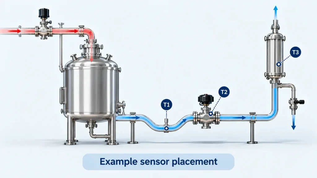
For the process steps behind SIP, see our posts on the SIP system and the clean-in-place system. If the plant is deciding between a fixed and a portable unit, mobile versus fixed CIP/SIP skids sets out the trade-offs.
Closed processing, filtration and vent filters
Annex 1 favours closed or enclosed processing where it is practical, and expects the filtration system to be designed so that it can be tested and monitored. Paragraph 8.82 addresses the design of the filtration system, 8.87 covers integrity testing of the sterilised filter assembly before use (PUPSIT) and after use, and 8.88 covers the integrity of vent filters. For the equipment supplier, the practical points are:
- Filter housings that can be steamed in place and drained.
- Test connections that are accessible without breaking the sterile boundary.
- Vent filters at vessel and line high points, with the flow and condensate path defined.
- A clear description of which components are inside and outside the sterile boundary.
Our post on why PUPSIT matters in sterile filtration covers the test itself. Where a plant wants fewer single points of failure around the filter and hold stage, the discussion in redundancy in sterile pharma manufacturing is relevant, and the production process of sterile injectables shows where these steps sit in the line.
Documentation that feeds the contamination control strategy
Annex 1 relies on records that show what was built, how it was tested and how it is maintained. For a vessel or skid, the set that the site QA team will want to see includes:
- URS, design specification and P&IDs with revision history.
- Material and finish records for product contact parts, with the weld documentation.
- FAT and SAT protocols and reports, including SIP and cleaning cycle records.
- IQ, OQ and PQ protocols, or equivalent qualification support.
- Software and automation documentation. Electronic records are covered by Annex 11 and 21 CFR Part 11, as explained in 21 CFR Part 11 and Annex 11 for process skid automation.
- Calibration and maintenance instructions for the instruments on the skid.
Annex 15 sets out how these documents fit into design, installation, operational and performance qualification. Annex 15 paragraph 3.6 allows FAT results to be accepted at site where justified, which is one reason a well documented FAT matters. The FAT and SAT guide for process skids explains what to test and what to insist on. For material and finish questions, see decoding ASME BPE standards for sterile manufacturing vessels.
A five-step gap assessment for existing equipment
A plant that already runs vessels and skids can assess them against Annex 1 without stopping production.
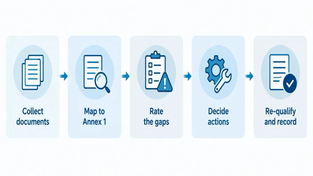
- Collect the documents. URS, P&IDs, qualification reports, SIP and cleaning records, maintenance history.
- Map them to Annex 1. Use the table above as a starting list, and note which paragraphs have no supporting record.
- Rate each gap by risk. Ask whether the gap affects the sterile boundary, product contact or the ability to prove a state.
- Decide actions. Options include added documentation, added sensors, a design change, or a replacement. Document the reasoning for gaps that you decide to accept.
- Re-qualify and record. Update qualification and change control records, and feed the outcome into the CCS.
For projects that are being planned now, the process skid procurement checklist shows where these checks sit in the buying process.
Frequently asked questions
Is steam-in-place mandatory under Annex 1?
Annex 1 does not name SIP as the only acceptable method. It expects product contact parts and connections to be sterilised by a validated method, and steam is the usual choice for stainless steel process equipment. Where SIP is used, paragraphs 8.58 and 8.63 expect it to be validated and monitored.
Is PUPSIT required?
Paragraph 8.87 sets out the expectations for integrity testing of the sterilised filter assembly before use and after use. The decision on the pre-use test should be documented and justified within the site’s CCS. Read the paragraph in full with your QA team before deciding.
Does Annex 1 apply to non-sterile products?
Annex 1 applies to the manufacture of sterile products. A site making both sterile and non-sterile products applies it to the sterile lines. Equipment on other lines follows the parts of EU GMP that apply to them.
Who owns the contamination control strategy?
The manufacturer. The CCS is a site-level document. The equipment supplier provides design information, qualification records and operating limits that the site uses in it.
What is the difference between Annex 1, Annex 15 and Annex 11?
Annex 1 covers sterile manufacturing. Annex 15 covers qualification and validation, including design qualification, FAT, SAT, installation, operational and performance qualification, and cleaning validation. Annex 11 covers computerised systems. A sterile skid project needs all three.
Can an existing vessel or skid be brought in line with Annex 1?
Often the first step is documentation and sensor placement rather than replacement. A gap assessment, as described above, shows where the real risk sits before any equipment decision is made.